Winches and Capstans
About Winches and Capstans
Winches and capstans have been known since the early days of civilisation, and have played an unseen but very important role in creating the world as we know it.
The construction of castles, cathedrals, mining, but also the discovery of the new world would have been much more cumbersome without winches and capstans. In today’s world winches and capstans are still very much present as the driving force behind elevators, diving cages, hoisting winches in modern telescopic cranes, or pulling winches in shunting- and shipyards and play an important role in keeping the world as we know it on the move.
Just as with building cathedrals, winches are still indispensable with building todays “cathedrals” as high rise buildings, bridges, drilling rigs and wind turbines.;
Winching for everyone
In essence a winch or capstan is a pretty basic piece of equipment, in wich a rope is wound around a tube, with the aim to lift or pull a load with relative ease. This publication is not only aimed at people with a technical background in winching, but is also intended at people only indirectly involved with winches or capstans and people who simply want to know more about the subject for any reason. To make sure our products and their technical capabilities are better understood, a basic explanation of what there is worth knowing about winches is provided in this publication;
Basic principles
If an object is lifted straight up it is called Hoisting.
Take note:
We are talking about hoisting here, but we are not talking about hoists!
The difference between a winch and a hoist is that a winch pulls the load via a sheave, the hoist pulls it straight on the drum.
Some EMCÉ winches are used as hoists, but are not specifically designed for this.
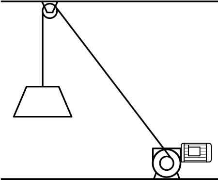
Figure Lifting
If the object is moved over level ground its called Haulage
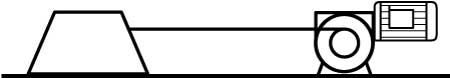
Figure Hauling
Determining line pull is easy as long as it is lifting.
Its simply the weight of the object, but if sheaves and or blocks are used the friction of these sheaves (ca 3 - 5% per sheave).
Pulling, also called haulage, is the difficult one.
The line pull depends on the weight of the object, the friction between the object and the floor and the incline it is pulled against (if any). Try to find out what the required line pull is, or when unspecified, how the job is done at the moment. With critical jobs a test with a pull meter (load cell) is recommended, this also applies to rolling stock or other items that are moved along rails.
With loads that are on railway carts (or carts on solid tyres on a smooth surface), the line pull is roughly ca. 1-2% of the dead weight of the load (combined weight of rolling stock and payload), but be aware if the track is at an incline or has an acute bend in it, the required force will go up very quickly.
In case of doubt about lifting or pulling, imagine the winch rope is being cut. Will the load remain stationary you are pulling, If the load starts to move, you are lifting.
Determining line pull is easy as long as it is lifting.
Its simply the weight of the object, but if sheaves and or blocks are used the friction of these sheaves
(ca 3 - 5% per sheave).
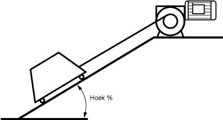
Figure Pulling against an incline
Figure correlation between line pull and track incline
| Line pull [kg] | Incline in [%] | Line pull in [kg] | |
|---|---|---|---|
| 5 | 45 | 55 | 440 |
| 10 | 90 | 60 | 467 |
| 15 | 135 | 65 | 494 |
| 20 | 180 | 70 | 522 |
| 25 | 222 | 75 | 545 |
| 30 | 262 | 80 | 569 |
| 35 | 300 | 85 | 590 |
| 40 | 338 | 90 | 610 |
| 45 | 374 | 95 | 627 |
| 50(22,5º) | 408 | 100(45º) | 639 |
Correlation between line pull and track incline (1 tonne load)
See the section "Calculation notes" for a more detailed explanation of this subject.
Motive power
With the line pull now determined, the motive power must be determined. Two most important factors to determine the motive power are linepull, or more accurately the required torque to achieve this line pull with the actual drum diameter in Nm, and speed to calculate the required power in kW.
Power and Torque
The essence of winching is to move objects from one position to another by means of a length of rope fixed to the object at one end and winding the other end on a rotating drum.The driving forces behind all this are called Power and Torque. Force is expressed in Newton (N) Formerly and still expressed in kg (kilogram) 1 kg = 9,81 N . We calculate with 1 kg =10 N. Power is expressed in kilo Watts (kW) formerly expressed in Horsepower. Torque in Newton metres (Nm) formerly expressed in kilogram metres or foot pounds.
Physics
As discussed power is expressed in kW (kilowatt). Physics learn us that Watt can also be expressed in J/s (Joule/second).
Joules expresse energie, also in Nm (Newton meter). Therefore Power can be expressed in Nm/s.This makes the power more understandable, since we know Nm (line pull x drum radius *1 ) and speed. The higher the speed, the more energy (Nm) we will have to put in per second, the higher the power.
See the section "Calculation notes" for a more detailed explanation of this subject.
Selecting the motive power
In the process of picking the right winch from the EMCÉ catalogue, or selecting the right motor for your application, we first have to decide what type of motive power is to be used
In the EMCÉ programme 3 types of motor are used.
- Electric
- Hydraulic
- Pneumatic
When the choice of motive power is determined either trough technical preference or trough existing infrastructure the choice of motive power is clear. If this is not the case, the motive power must be selected on merit.
4.1) Electric
Always try electric first. All the virtues that the other two have can be mimicked by electric motors. Explosion or water proofing, braking or speed control it can all be done with an electric motor. In most places there is direct access to the main grid, and if this has proven to be reliable this is the best way to drive a winch. Electric motors tend to be very economical for their performance, but of course the price goes up with size. Even really big motors are very competitive against hydraulic ones since their power pack would need an even bigger electric motor. Although the price of the control box goes up with the motor size (especially so with;frequency control of the speed) the motor control box price is always competitive against a motor/power pack arrangement.
4.2) Hydraulic (Oil)
For a very compact motor with high torque and power and full speed control at maximum torque the hydraulic motor is not to beat.The motors themselves are relatively cheap for their power, but an electro- or diesel hydraulic power pack is needed to power the winch.These power packs can be quite expensive, with the price rising dramatically if high flow rates are needed.The cost of this power pack and the associated piping has to be added to that of the winch. If hydraulic power is already available on the site, this gives the hydraulic motor both the technical and commercial edge over other options. Also if from a single power source several winches can be operated this can prove to be an economical alternative to installing several big electric motors in particular when the winches are used intermittantly.
4.3) Pneumatic (Air)
For motors that are at their best in areas with (high) risk of explosions as in the petroleum, mining and some process industries go pneumatic.
They are expensive for their power output and only go up to 22 kW, and are not suitable for high power applications. Also you need quite a sizeable compressor unit to power the bigger motors at any serious speed, which can be quite expensive. As outlined with hydraulics if compressed air is already available in sufficient quantities this is not an issue. For full understanding of the specific properties of the different motors and their sub types please check the relevant catalogue section or contact the EMCÉ dealernetwork or sales office.
Selecting the transmission
The transmissions used in the standard EMCÉ programme are selected to provide the proper balance between cost, durability and suitability. If however we have to venture outside the catalogue offerings more calculations are needed. In selecting the type of transmission the most important question is how much torque has the transmission to transmit.To calculate this torque we use a calculation we used before albeit with a slight modification, since gear ratio and transmission efficiency are not relevant for this calculation. line pull (in N) x drum radius*1 (in m)= torque in N/m
*1) drum radius is to be seen as the actual distance from the top layer rope to the centreline of the drum.
As can be seen again the drum diameter (or the number of layers on the drum) influence not only on the motor selection but also the gearbox selection.
As can be expected there are advantages and dis-advantages associated with the different types of transmissions, we will each treat them in turn:
5.1) Wormgear transmissions
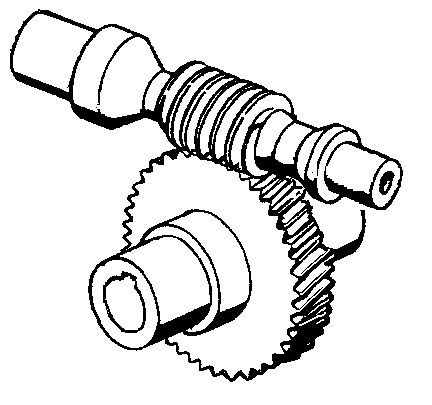
Figure Worm and Wormgear
| In favour | Against |
|---|---|
| Low cost - Self locking (high ratios) | Poor efficiency at start up (high ratios) |
| Easy to integrate | Acceptable efficiency running (high ratios) |
| Can be fitted with emergency hand wheel or crank | Choice of ratios limited |
| Simple | Choice of ratios limited |
| - | Limitations to motor power and max. motor speed (1500 rpm) |
| - | Not suitable for continuous use |
The wormgear transmission is used in winches up to ca 2,5 tonne capacity.The actual limit is decided by maximum allowed torque value of the worm gearbox in question.The self-locking action is the positive side of the Achilles heel of the worm gear box its efficiency. The higher the gear ratio the more power loss (up to 50% in some cases) is incurred. An other feature is the so-called "static stiction". The normal running losses assume the presence of an oil film between worm and worm gear. At start up this film is not present, and the power losses momentarily (fraction of a second) shoot up to sometimes no less than 80% of what we put in. In the calculations for motor power and torque these losses must be included, as has been done with all EMCÉ winches.
5.2) Planetary transmissions
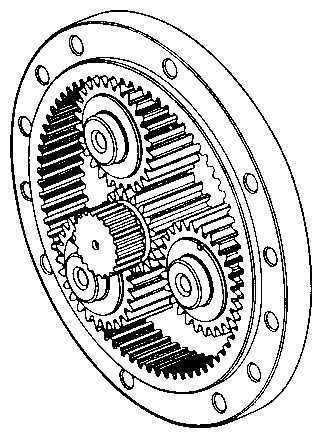
Figure Planetary stage
| In favour | Against |
|---|---|
| Very good efficiency | Higher cost |
| Very high power inputs | More complicated |
| Very high torque values | Brake required |
| Very wide range of ratios | More difficult to integrate |
| Suitable for continous operation | - |
The planetary transmission is used in winches of all capacities, but typically for winches above 1,5 tonne lifting capacity, or in winches with high speed requirements.There are no serious limitations to the torque values and input speeds of these units. Planetary gear boxes are of a modular design. The gear box ratio can be varied indefinitely by the combination of these modules (so called stages) each with different ratios.The gearbox always will include the so called output shaft and input shaft. Between those two the stages (anything between 1 to 4 stages) are "sandwiched". The higher ratio is required the more stages are fitted. Gear ratios between 4:1 up to 2.500:1 can be built from this Meccano box system. This will increase length, weight, oil capacity and cost of the transmission. Also the power loss in the transmission increases with the number of stages. A reduction in efficiency of ca. 2-3% per stage is considered normal. The fact that these transmissions are not self locking is no problem, since for winch use the following brake methods can be used.
Electric Pneumatic drum or transmission brake
Fitting a brake is of course a cost factor, but is included in the standard price of the EMCÉ planetary winch. To improve on the price of a haulage winch in some cases the brake can be dispensed with leading to a price reduction of the winch. Contact EMCÉ for advise in these cases. Alternatively a combination of a planetary gearbox fitted with a worm gear box on the input side can provide the required brake action. Of course the combined gear ratio of the two gear boxes is the one used for calculations. Due to the high overall ratios with these combinations this solution is really only suitable for low winching speeds.
5.3) Spur Gear transmissions
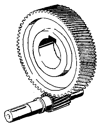
Figure Spur gear transmissions
| In favour | Against |
|---|---|
| Cheap | Limited range of ratios |
| Very good efficiency | Not self locking |
| Compact | Limitations to motor power |
| Simple | - |
The spur gear transmission is only used in winches as a step-down gear box in combination with a worm gearbox. Its purpose is to increase the overall gear ratio over that available from the worm gearbox alone.
Uses are:
- Achieving very slow winching speeds
- Reducing the motor speed of air motors to an acceptable level for the worm gear box and increase the available torque from them.
- Making the most out of the torque available from single phase electric or air motors.
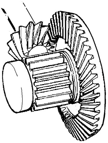
5.4) Bevel Gear transmissions
| In favour | Against |
|---|---|
| Good efficiency | Not self locking |
| Wide range of ratios | Limitations to motor power |
| Suitable for continuous use | Longer lead time |
| Relatively economic | - |
The bevel gear transmission is used as a primary gearbox in winches, but can also be used as the last stage in a planetary gearbox to save space. Power loss from these boxes is ca. 3%.
Selection of winch model
Now armed with the theoretical background on gearboxes and motors, the type and model of winch can be undertaken.The selection of the model of winch governed by several parameters.
- type of transmission
- drum capacity
- additional equipment (band brakes, clutches, spoolers etc.)
- size requirements that follow from the application.
In the catalogue section of this publication the available options, capacities and dimensions are given for each winch type.
Winch construction details
With one or two winch models now selected, it is time to explain the finer details of winch construction, and how design choices will determine the suitability of the winch for the task at hand. The centre piece of the winch structure is the drum.
The drum
This takes us to another important value in winching ,drum capacity. It is most likely the total amount of rope that should be stored on the drum is known, if not the standard rope capacity available for the winch selected from the catalogue can be used. If however a certain drum capacity is needed, it must be checked if the standard drum of the type selected can be used, or that this needs to be lengthened its diameter increased (which may require a stronger gearbox) or even have a look at another model of winch.
Assuming we use the drum diameter specified for the selected type we have two more dimensions that govern the drum capacity.These are: a) width (how many rope windings fit side by side on the drum) b) flange diameter (how high can we stack the ropes).
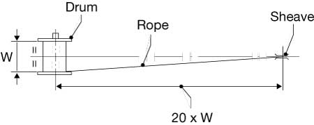
At a given drum diameter and number of layers increasing the width will increase the drum capacity making it narrower will reduce the capacity. winch performance will be the same to the original 3 layer performance. On the negative side (considerably) wider drums need a correspondingly larger distance to the first sheave to retain the desired fleet angle.
If this is not observed spooling behaviour will deteriorate in the same degree as the drum is made wider. Making the drum wider also increases the width of the winch with a similar amount.
At a given drum diameter and width increasing the number of layers will increase the drum capacity. There is a maximum to this, and the flange diameters are the governing dimension here. The flange dimensions are given in the catalogue section. It is important that at any given time the top layer on the drum is at least 2 rope diameters below the flange diameter.The winch performance will deteriorate with each extra layer wound on the drum. Also the line speed will increase with every extra layer wound on the drum. As we have seen already increasing the speed requires more power if we do not reduce the line pull. On top of this we get further and further from the drum centre with every layer therewith increasing the torque requirements for both gear box and motor, unless we reduce the line pull. Also spooling behaviour will deteriorate with increasing the number of rope layers, and in cases with a great number of layers a spooling device might be needed.
The standard drum sizes in the EMCÉ programme are a happy medium between rope capacity, pulling power and size. The choice on how to increase the capacity is greatly dependant on the situation, but in most cases widening the drum is the easiest and cheapest way to solve the problem. Doing so the motor and the gearbox of the original winch can be retained only more drum and frame have to be added. Take care however that with widening the drum the spooling behaviour deteriorates., and in extreme cases a spooling device is needed. Note ) the drum width and its diameter can not be altered on the FD and TN models. A bigger or different model of winch has to be selected in these cases.
Location of the anchor point on the drum
The drum must be fitted with a means of fixing the rope to the drum the so called anchor point. This anchor point can take several forms. Anchor points on outside of the drum flange. a) Clamp type: clamps the rope by means a block that is tightened with bolts this is the method preferred by Emce since it allows control over the clamping action. b) Wedge type: rope is folded around a wedge that is jammed in a pocket and is pulled tighter under load. Anchor points in the drum surface c)Bolt type: clamps the rope in a chamber in the drum, this is an elaborate system and should only be used with split drum winches with two ropes. For certain man made fibre ropes alternative means of fastening are required, contact Emce if in doubt.
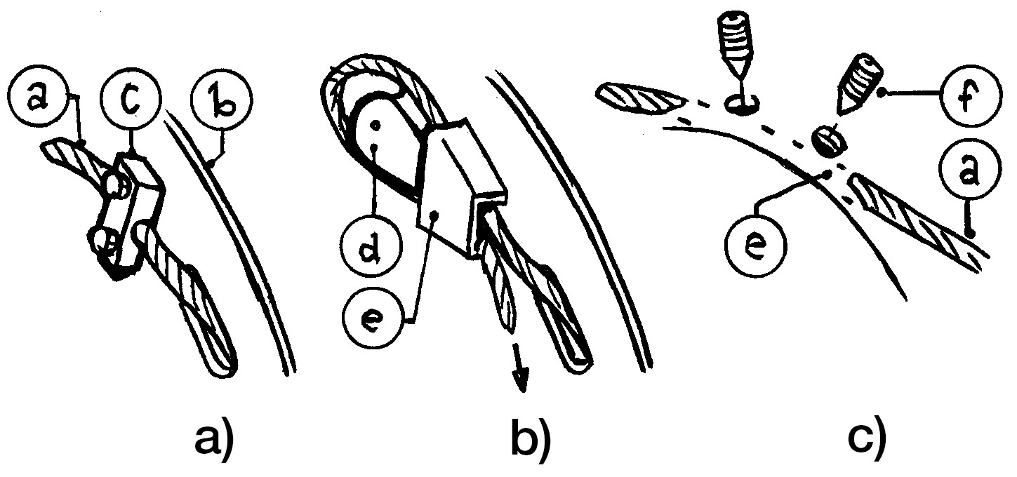
Rope anchors
The location of these anchor points is not arbitrary. It is determined by cable lay and on how the rope comes of the drum.The way the rope comes of the drum is based on the use of the winch and how it is installed, which is usually dictated by the end user. First of all we distinguish top run of and bottom run off see figure Drum-Rope-Sheave
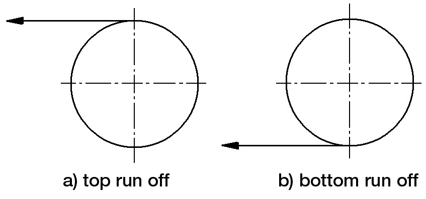
Top and Bottom run off
After deciding for top or bottom run off we must fix the anchor point to the side of the drum which is in keeping with the lay of a RH laid rope.
Always use RH laid rope unless there is no real other option. LH rope is hard(er) to obtain, there is not much choice and it is more expensive. To understand the role of the direction of lay in rope behaviour it must be briefly addressed. We must see a rope as a collection of bundles of very thin steel rods wound around one and other and the bundles around one and other again. As a result of this the rope wants to wind even tighter as it is tensioned, but only if it is clamped down in accordance with its lay. In itself this is a good thing for we do not want the rope to unwind. If it is clamped down against its lay it will be pulled open, which will lead to an early failure of the rope. See figure for the differences between RH and LH rope
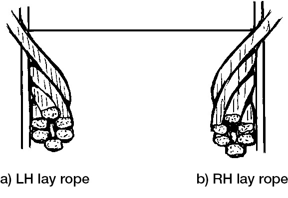
RH and LH rope lay
This desire to rotate also influences spooling behaviour. If fitted correctly to the drum the rope wants to wind itself as tightly as possible against the previous winding, therewith ensuring uniform winding of the rope. This is very important in its own right, but is crucial when 2 or more layers are to be wound on the drum. If the anchor point is not correctly located for the lay of the rope this will manifest itself as uneven winding with gaps between the separate windings. This is caused by the rope wanting to rotate away from the anchor point instead of towards it.
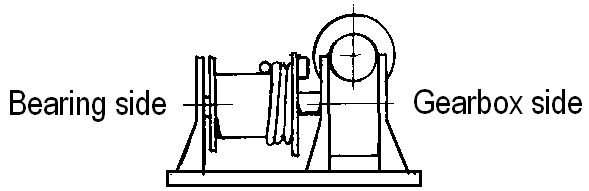
If “non rotating” or “spin free” rope is used (which is very strongly recommended for hoisting purposes) this pehenomenon will not be present or only in a very much reduced form. In most winch types there is freedom of choice where to locate the anchor point on the drum so RH laid rope can be used to good effect. The two different sides of the drum are referred to as ‘transmission side anchor’ or alternatively a ‘bearing side anchor’
Defenition of winch sides
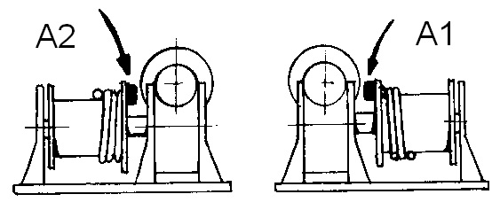
In some cases we can not freely choose the location of the anchor point due to limitations set by the winch construction (e.g.FD and standard wormgear winches), see figure.
Handing of winches
In most cases we can rotate the winch or simply have the drum fitted to the other side of the winch to overcome problems with installing the winch on the work location. Only in cases this is not possible for some reason or another LH lay rope should be necessary.
Grooving
In some cases it is necessary or required to groove the drum.The advantage of grooving is that the individual windings of the rope are better supported and will prevent scrubbing of the rope windings. Doing so both spooling behaviour and cable wear are greatly improved.
This effect can be further enhanced by the addition of a pressure roller. The improvement in spooling will manifest itself most significantly on the first layer, but is also important for subsequent layers. For some winches like man riding winches the grooving can be a legal requirement. Make sure if a legal requirement exist, for it may prove that both grooving and single layer drum use required. Grooving can in most cases only be done at the production stage since a greater wall thickness of the drum tube has to be used. Alternatively grooved shells can be used afterwards if no other solution is practical. When a drum has to be grooved, it must be absolutely clear if RH or LH lay cable is used, since the grooving direction is dependant on the cable used. RH lay cable needs LH grooving, with LH lay rope it is the other way around.They can not be interchanged.
Top and bottom run off do not influence the handing of the grooving, providing the winch can be positioned in such a way the rope points in the right direction.
There is also a type of rope that combines the characteristics of LH and RH laid rope since it is made of both RH and LH strands.This rope is called ‘spin free’ in its most advanced form and ‘spin reduced’ in a more economical version. Never the less even these ropes still have a residual tendency to spin, and are still handed to some extent. Spin free or spin reduced rope is recommended for use in hosting applications, with the advantages becoming more apparent with increasing hoisting hights.
Fleet angle
The single most important factor in the spooling behaviour of a winch is the fleet angle of the rope. This is not so much a function of the winch itself, but of the distance from the winch to the first sheave the rope is running on.The fleet angle or in other words the angle between the centreline of the rope and a straight angle on the drum. The fleet angle is not a very rigid one, and varies between grooved and smooth drums.In general the following values are used. Smooth drums 20 - 55 times the drum width. Grooved drums 15 - 55 times the drum width. With deciding on the fleet angle of grooved drums the angle of the grooving also has to be taken into account. In fig. 7.4-1 fleet angle is illustrated.
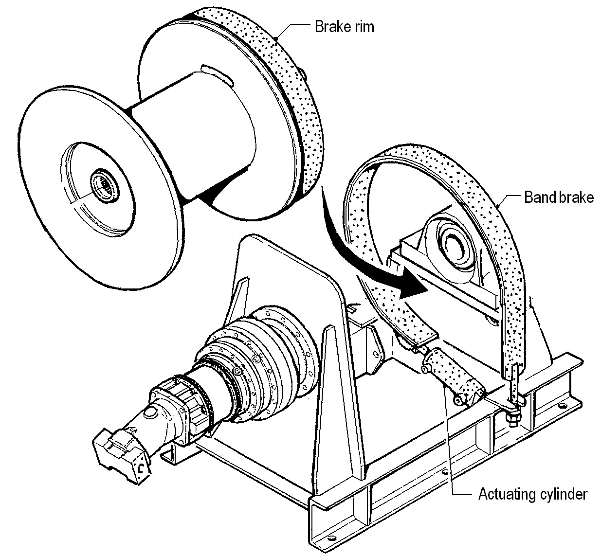
Band brake
A band brake can be fitted to most EMCÉ winches that have a drum supported on both sides. A band brake is, as the name suggests, a steel band lined with a brake material, that can be pulled tight against a rim on the winch drum. The band brake is attached to the frame, and the execution of this attachment is dependant on the rope run off (bottom or top). The band brake can be actuated by a manually operated spindle, an over centre lever or hydraulic or pneumatic cylinders. With a separate band brake it is possible to have (much) higher holding forces than on the transmission or motor brake.The most common use is for anchor or mooring winches in a marine environment. Take note that the winch will be wider with a band brake than standard.
Clutch
As with the brakes a clutch can be fitted to most winches that have a drum supported on both sides. Depending on the size of the winch a claw or multi pin clutch is used, in most cases operated by a manual lever. Other modes of operation on request.
As a rule winches with a clutch should not be used for lifting purposes, and in most cases should be fitted with a band brake (see above) to hold the load.Take note that the winch will be wider with a clutch than standard. (See section 6 selection of winch model on availability.
Spooling gear
To improve spooling of the rope in situations were a normal fleet angle can not be maintained or in cases were a very large number of layers is used a spooling device can be used. In essence a spooling gear consists of two guiderollers, that move along side of the drum to guide the rope while spooling. The drive in most cases is taken of the drum itself by means of a roller chain. The chain drives a double helix shaft on which a finger translates the rotation in sideways movement. The real trick with spooling double helix shafts is that without changing the rotation direction of drum and spindle the finger must change the direction of travel when the end of the drum is reached.
Only a hand full of companies can produce helix shafts of good quality, and their production is quite labour intensive.
Fitting a spooling gear to a winch is therefore quite an expensive exercise.
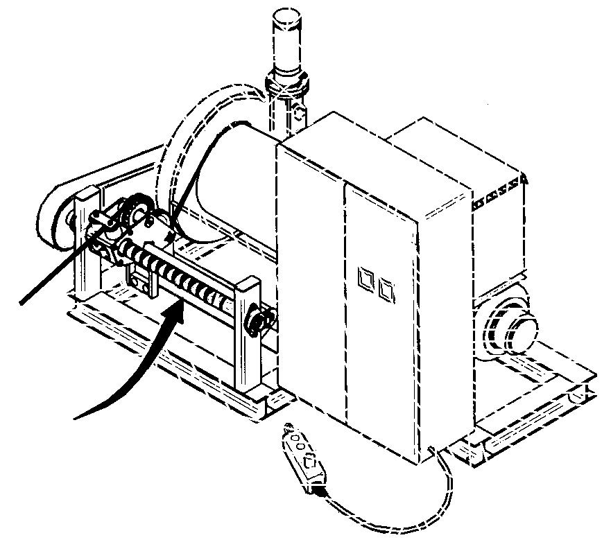
Typical spooling gear installation
An alternative for helix shaft bases systems is the electrically driven spooler gear.Here a threaded shaft and nut that is driven by a separate motor and gearbox. Back and forth movement is not a function of the spooler shaft, but of a PLC programme that steers the spooler shaft drive motor in one direction, and the end of the spooler stroke reverses the procedure.This set up requires a more complex control box and the use of an encoder on both the main drive motor and the spooler motor. Cost is slightly higher than a conventional system, but the electronic system offers a number of advantages such as dynamic layer dependant spooling, rope length measuring and infinite adjustment possibilities to get the right "gear ratio"between drum and spooler.
Winch frame
To put it a bit un politely the sole purpose in life for the winch frame is to keep all the other bits together and keep them attached to the floor.
This means the most important requirement for a winch frame is sturdiness. For the standard Emce range the frames are optimised for their intended use and in most cases the frame is what sets the winches apart. For special winches when size or weight requirements play a role special frames can be designed and constructed. In these cases EMCÉ is more than happy to design as per requirement.
Surface protection
With the winch model now defined, motive power, transmission, drum and frame type selected. The only thing we have to do is make sure we apply a suitable form of corrosion protection for the application at hand. In most cases this takes the form of a paint system, but galvanizing or constructing the equipment from corrossion resistant steels, or a combination of the tree options, is also possible. As per intended use the type of paint and final layer thickness will differ.
The standard finish for all EMCÉ winches is:Base metal is cleaned with solvent, after drying two subsequent layers of a one component paint are applied.The dry film thickness is ca 80 um. Standard colour is blue RAL 5010, all other colours are an extra cost option.
Paint systems according to customer requirements can be provided at extra cost.
Consult the EMCÉ dealernetwork or sales office for more information.
Controls
The winch is ready now including a fresh coat of paint.Most users want some form of control fitted to the winch, others will install their own controls.This leads us to the control options.
Electrical control options
Standard control box
In its most basic form the controls for an electric winch consist of a simple box with push buttons.
The box can be mounted on the winch or near the winch.The buttons on the control box are up--down and emergency stop. Inside we will find a thermical unit that makes sure we don’t over load the motor. The cost of the control box is not include in the winch price.
Remote control options
Another popular addition to the standard box is the remote control. This takes the form of a hand held control panel that is connected to the control box by a length of cable. A standard part with this is a transformer that reduces the motor current to a safer 24 volts, just in case.
With a remote control the buttons on the box are dispensed with. If buttons are required on the box this is an extra cost option that must be combined with a selector switch to select either the remote or the buttons on the box.
Alternatively 2 or more remote control units, radio control units or proximity switches can be used, but always in combination with a selector switch. A special form of remote control is the foot pedal which is mostly used with capstans.
Load limiter
For hoisting winches over 1 tonne capacity an electronic load limiter is required in the EC.This is fitted in the control box, and measures the current drawn by the motor. Since there is a direct correlation between current draw and power production of the motor we can limit the performance of the motor and therewith the line pull. The limiters are adjusted in our works on the test tower with the actual maximum load being hoisted by the winch.
Limit switches
The winch movement can be controlled by limit switches, there are twi type of limit switch. One
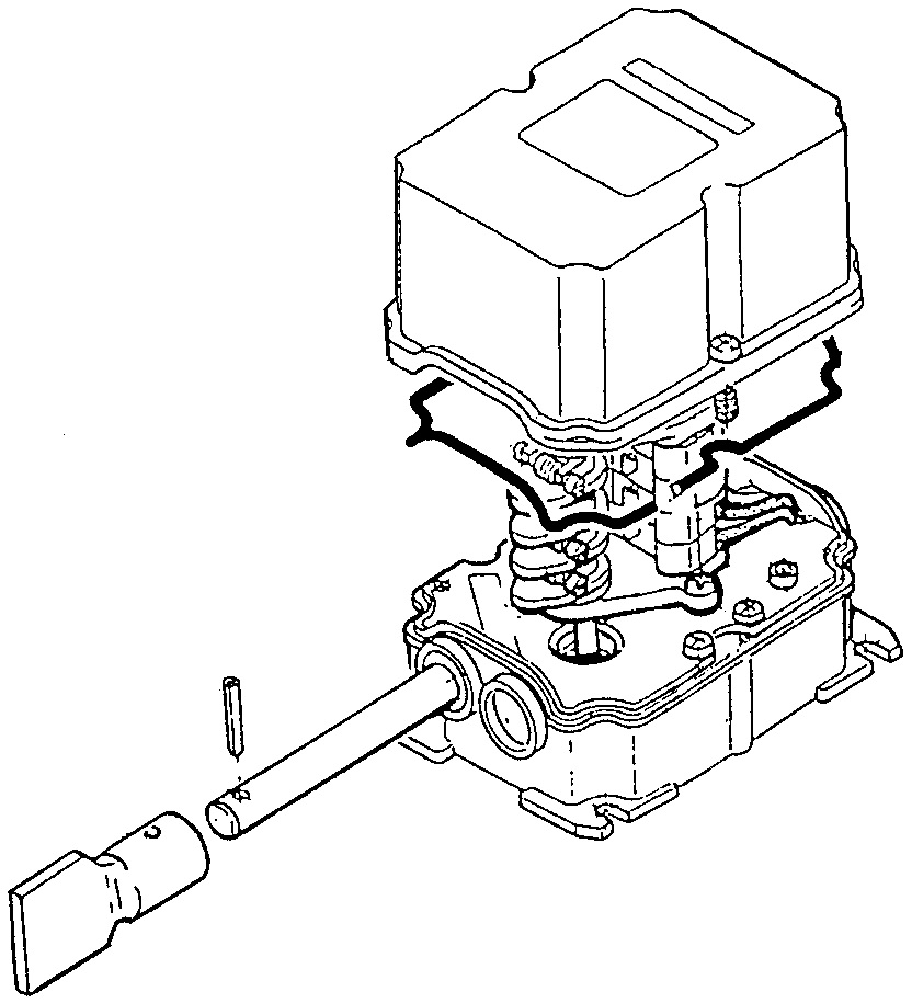
Spindle limit switch
This is the most simple type, and is fitted to the drum shaft. It counts the number of drum revolutions, which equate a given amount of rope being paid in or out.The are easy to fit to the winch, can be fitted with up to 8 contacts.The switches operated on the wormgear principle, and therefore must be matched to the drum diameter. Different ratios are available. If very accurate positioning is required these switches can not be used.
Variations in rope position up to 30 - 40 centimetres can occur. More accurate spur- or planetarygear spindle limit switches are available, that can also be had in extreme gear ratios and high IP classes. Adjustment is straight forward by rotating the cams that lift the contacts in relation to the drum.
Proximity limit switches (mechanical type)
These switches simply rely on the hoisted object pushing in the roller arm on the switch, therewith breaking the circuit to the winch.Two of these should be fitted one upper limit, one lower limit switch.
Proximity limit switches (optical / magnetic type)
Again reacts to the hoisted object, but instead of physical contact between switch and object, it relies on the switch ‘sensing’ the proximity of the object either by seeing it with infra red or visible light or noticing changes in the magnetic field.
Advanced controls
For certain applications more advanced controls are needed.
The most common is the frequency inverter control. As its name already suggests this controls the frequency at with the motor runs.The nominal frequency is either 50 or 60 Hz, which can be reduced to ca 20 Hz for low speed operation. Alternatively the frequency can be increased over the nominal value, but this at the cost of both torque and power. All options as mentioned under the normal control box can be used apart from the load limiter. The frequency control itself is limiting the maximum current flow.
Hydraulic control options
The hydraulic controls take the shape of a hydraulic valve.This valve provides control over both speed and direction of the winch. In most cases these valves are not part of the winch delivery. The valve can be fitted on the winch or in another suitable location. Another control option (or necessity rather) is the brake shuttle valve. This valve operates the fail safe brake (if fitted) and makes sure the brake is applied if the hydraulic pressure falls below a certain pre set value, and is released if the pressure is restored. The valve monitors pressure at both sides of the motor to check the direction of rotation.
Pneumatic control options
What is said with hydraulic controls also applies to pneumatic controls. In most cases these valves are part of the winch delivery. The valve must be fitted on the winch or in its immediate vicinity. This is necessary in view of a possible pressure drop if control lines get to long. An other option is a remote control valve (RCV) that is connected to a remote control unit by means of small hoses to the actual valve on the motor.
As with the hydraulic controls a brake valve is needed for hoisting application. This also operates the brake at the moment the pressure drops below a pre set figure. Limit switches (small pneumatic valves) can also be used with pneumatic winches. In case a spindle limit switch is used, this is fabricated in our factory using a very small worm gear box. The cost of these units is much higher than the electrical ones, which are standard units from normal commercial sources.