Winch type AW 1000 LS
| Product code | EMAW1000LS |
|---|---|
| Manufacturer code | AW 1000 LS |
| Medium | Pneumatic |
| Environment | Marine |
| Application | Lifting |
| Series | AW-series |
| Working Load Limit (WLL) [kg] | 1000 kg |
| medium | Pneumatic |
|---|---|
| environment | Marine |
| application | Lifting |
| series | AW-series |
| working Load Limit (WLL) [kg] | 1000 kg |
| number of layers | 3 |
| lifting WLL top layer | 1000 kg |
| speed at first layer | 6.5 m/min |
| drum capacity top layer | 40 m |
| rope diameter | 10 mm |
| holding force | 3000 kg |
| mass | 195 kg |
| pressure drop | 6 bar |
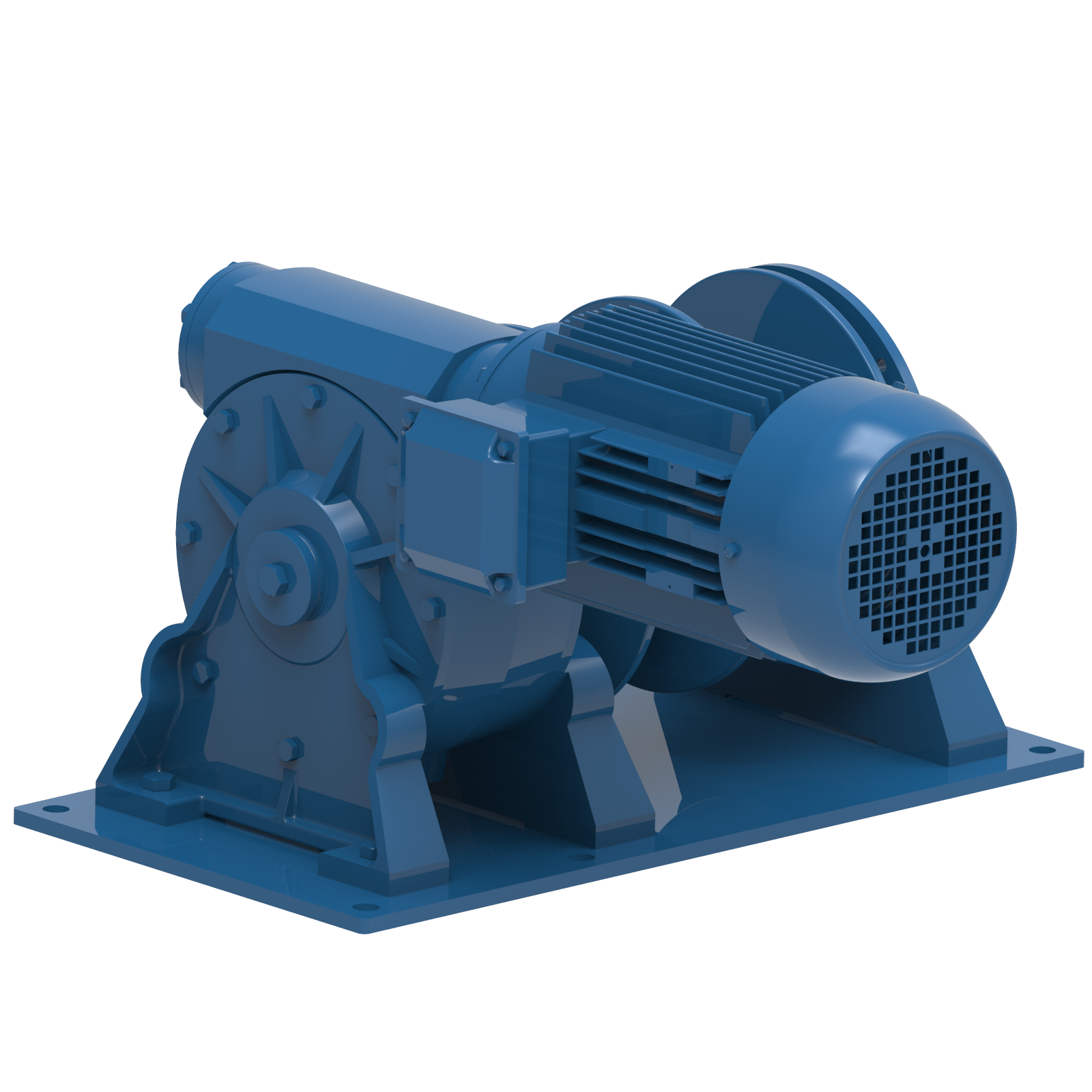
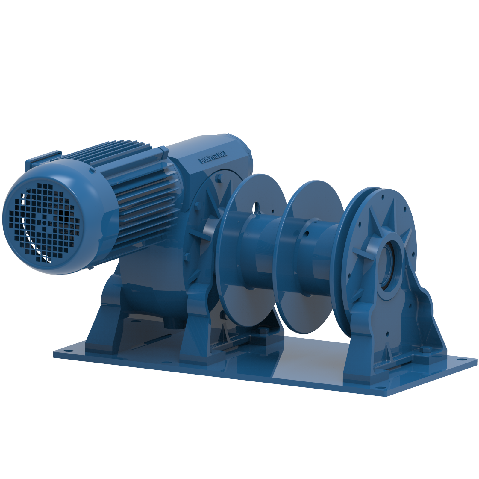
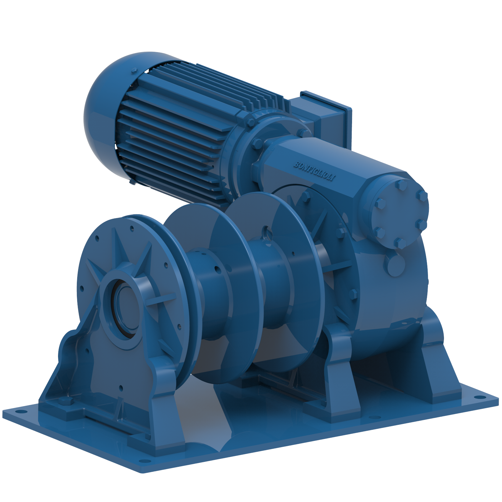
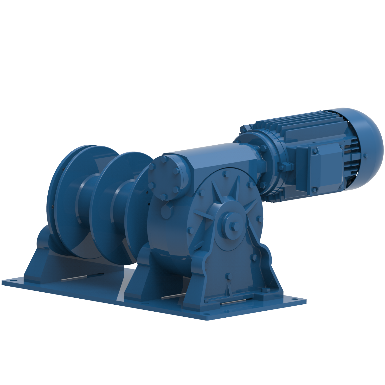
Drawing

AW winches are designed to position and hold accommodation and ship-to-shore ladders and ladders between vessels and offshore installations. Constructed in accordance with SOLAS requirements for international shipping, the range features a dynamically and statically self-braking wormgear and emergency hand crank. Each type may be configured for single or twin rope operation and powered by means of an electric or pneumatic motor. PW winches are used to lower and lift the pilot ladder on board of seagoing vessels, EMCE has one standard design, PW 550, that has been supplied to several dredging vessel fleet owners. We have also supplied custom-built designs. Please ask about the available options.
Standard features
- Self-braking wormgear transmission for the AW series
- Planetary gear for PW 550
- SOLAS compliance
- IP 56 TENV motor protection for the AW ES series
- IP 66 TENV with standstill heating for the PW 550
- Rotary vane, gear type air or motor for the AW LS series
- Steel drum (not grooved) with one or two cable fixing point(s) at flange
- Two drum supports
- Emergency hand crank for the AW series only
- Double layer 2-component conservation, colour RAL 5010
- 13 meter pilot ladder with 32 fl at steps, 4 spreaders and 4 rubber steps for PW 550
- Pneumatic versions with hand control valve
- IP 66 spindle limit switch for PW 550
- FEM / ISO class: T3-L3-M4
Note: For pneumatic winches is the speed on the first layer the average speed. The speed at the top layer is at unloaded conditions.
Mechanical options
- Band brake, manual or automatic fail-safe for the AW series
- Increased motor protection IP 68 TENV for the AW series
- Alternative supply voltages
- Grooved drum for AW series only
- Drum pressure roller for AW series only
- Alternative speeds
- Alternative drum dimensions / split drums / additional rope anchors / etc.
- Drum guard for AW series only
- Marine / offshore coating systems
- Class witness certificates
Control options
- Electric or pneumatic control systems
- Limit switches
- Load limiters